|
Interface
Conversion
|
USB
to RS232 conversion, self-powered inline, non isolated
USB232
|
|
USB to RS422/485 conversion, self-powered inline, isolated
USB485
Supports RS422, and 2-wire and 4-wire RS485
|
 |
|
RS232 to RS422 conversion, self-powered inline
 For
a PC with a 9-way RS232 port: For
a PC with a 9-way RS232 port:
K2
(non isolated). RTS and/or DTR signals should be at the HIGH level
to power the device.
K3
(isolated). RTS and/or DTR signals should be at the HIGH level
to power the device.
For
a PC with 25-way RS232 port:
K422-ISOL
(isolated). RTS and/or DTR signals should be at the HIGH level
to power the device.
|
|
|
RS232 to RS422 conversion, externally powered
DIN rail
For
any RS232 device, data transparent:
KD485-STD
(isolated). Requires +7V to +35V DC power.
|
|
|
RS232 to RS485 (4-wire) conversion for Master use, self-powered
For
a PC with a 9-way RS232 port:
K2
(non isolated). RTS and/or DTR signals should be at the HIGH level
to power the device.
K3
(isolated). RTS and/or DTR signals should be at the HIGH level
to power the device.
For
a PC with 25-way RS232 port:
K422-ISOL
(isolated). RTS and/or DTR signals should be at the HIGH level
to power the device.
|
|
|
RS232 to RS485 (4-wire) conversion for Master
use, externally powered
KD485-STD.
Requires +7V to +35V DC power.
|
|
|
RS232
to RS485 (2-wire) conversion, self-powered
For
a PC with a 9-way RS232 port:
K2
/ K2-ADE (non isolated). DTR should be at the HIGH level to
power the device. With K2, RTS controls data direction (the RS232
application must provide RTS Control);
with K2-ADE RTS should be permanently HIGH to provide additional
power.
K3
/ K3-ADE (isolated). DTR should be at the HIGH level to power
the device. With K3, RTS controls data direction (the RS232 application
must provide RTS Control); with K3-ADE
RTS should be permanently HIGH to provide additional power.
For
a PC with 25-way RS232 port:
K485-ISOL
(isolated). DTR should be at the HIGH level to power the device,
and RTS controls data direction (the RS232 application must provide
RTS Control).
|
|
|
|
RS232 to RS485 (2-wire) conversion, externally
powered
KD485-STD,
requires RTS Control of data direction.
KD485-ADE,
has automatic driver enable and does not require RTS control (use
Mode 1 built-in program)
|
|
|
Attaching non-addressable RS232 or RS422 devices
to an RS485 bus
KD485-ADE,
use Mode 2 built-in program. Up to around 30 devices can be multi-dropped
on one RS485 (2-wire or 4-wire) bus.
|
|
|
Attaching 2-wire RS485 Slaves to a RS422 (or
4-wire RS485) Master
KD485-ADE-422/422.
This is a special-order version with 422/485 interfaces on both
sides.
|
|
|
Using a K2-ADE for RS422
The
K2-ADE is intended for 2-wire RS485 but it is possible to use
it for RS422 (RS422 is an interface where the driver and receiver
are permanently enabled).
The
key is the note under Fig 5 (the dipswitch diagram) marked (*)
in the K2/K2-ADE
data sheet which explains the requirements. The requirement
for the RTS input to be LOW can be met in one of two ways:
a)
Ensure that the application software sets RTS=LOW in the initialisation
of the serial port (obviously this is possible only if you can
modify the application software), or
b)
Construct a simple cable for the RS232 connection between the
converter and the PC, containing only the following wires
2-2
3-3
4-4
5-5
This
cable ensures that there is no connection to RTS (pin 7).
|
|
Isolation Only
|
|
RS232
Isolation
Important:
before
ordering, check that the two RS232 devices to be interconnected
work together (with a short cable) with just the two data
lines (TX,RX) and GND interconnected (i.e. 3 wires total). This
ensures that the connection does not require the use of hardware
handshakes. This is also true for an RS422-RS422 connection although
hardware handshakes are rarely used there.
Inline,
Data Transparent:
K3-232
(for DB9 connectors) RTS and/or DTR (preferably both) signals
should be at the HIGH level to power the device - this is needed
on onse side only; the other side may have just TX,RX,GND connections..
K232-ISOL
(for DB25 connectors) RTS and/or DTR (preferably both) signals
should be at the HIGH level to power the device - this is needed
on onse side only; the other side may have just TX,RX,GND connections.
DIN
Rail mounted, data transparent:
KD485-STD-232-232
Requires +7V to +35V DC power.
DIN
Rail mounted, for baud rate / character format conversion:
KD485-ADE-232-232
Requires +7V to +35V DC power.
Data
Transparent, over Fibre
KDF-232-XX-XX
Requires +7V to +35V DC power.
|
|
|
RS422 Isolation - DIN Rail mounted
Data
Transparent:
KD485-STD-422-422
Requires +7V to +35V DC power.
Data
Transparent, over Fibre
KDF-422-XX-XX
Requires +7V to +35V DC power.
For
baud rate / character format conversion:
KD485-ADE-422-422
Requires +7V to +35V DC power.
|
|
|
RS485 Isolation - DIN Rail mounted
4-wire
RS485, with baud rate / character format conversion:
KD485-ADE-422-422
Requires +7V to +35V DC power.
2-wire
or 4-wire, over Fibre
KDF-422-XX-XX
Requires +7V to +35V DC power
|
|
RS232 Line Extension
|
|
If
you need isolation, please see "Isolation Only" above.
Important:
before
ordering, check that the two RS232 devices to be interconnected
work together (with a short cable) with just the two data
lines (TX,RX) and GND interconnected (i.e. 3 wires total). This
ensures that the connection does not require the use of hardware
handshakes.
If
you merely wish to extend an RS232 link without isolation, you can
use two RS232-RS422 converters connected back to back. The connections
between the converters' RS422 interfaces are:
TXA
-> RXA
TXB -> RXB
RXA <- TXA
RXB <- TXB
GND -- GND
Suitable
products are the K2, K3, K422-ISOL, KD485-STD. All but the K2 will
also provide isolation. The K2 and the KD485-STD will support up
to 115200 baud; the others are 38400 baud max.
|
|
|
Emerson
/ Control Techniques Drive RJ45 Interfacing
|
|
These
drives use 2-wire RS485, on an RJ45 connector. The RJ45 connections
are published in the drive manuals and we offer a converter cable
for our 2-wire RS485 inline interface converters: the CAB-030.
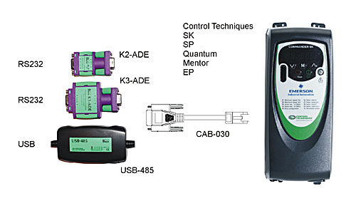
CAB-030
is 0.5m in length and connects directly to the K2-ADE,
K3-ADE or the USB-485.
It has been tested at up to 38400 baud with the Commander SK and
the supplied CTSoft drive control software. The Unidrive SP, Mentor
and other products use the same interface. The K2-ADE and K3-ADE
are configured for 2-wire RS485, transmitter and receiver both auto-controlled,
and usually for 19200 baud which is the default baud rate for most
CT drives.
The
3-way isolated DIN rail mounted KD485-ADE
can also be used in more "industrial" applications, with
Port 2 wired for 2-wire RS485, with the following connections:
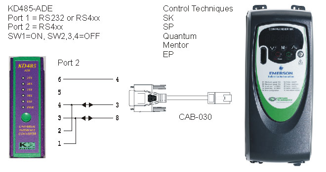
The
KD485-ADE is normally configured for 19200 baud, 8 bits/word, no
parity, 2 stop bits, Mode 1.
Some
Control Techniques drives can be configured for up to 115200 baud
which is supported by the USB-485 and the KD485-ADE. The K2-ADE
Option 01 also offers 115200 baud (not tested with the above drives).
The most notable aspect of the comms is two stop bits.
|
|
Protocol Conversion |
|
Applications
that require 1 or 2 ports
KD485-PROG
Two ports. Can be ordered with a combination of RS232, RS4xx,
20mA interfaces. 115200 baud debug output via a dedicated 3rd
output-only port. Programmed in C with an external compiler. MODBUS
RTU Slave library available.
|
|
Applications
that require 3 or 4 ports
PPC
/ PPC-E Four ports. Each port can be user populated to RS232
or RS4xx. Programmed in Pascal (built-in editor+compiler) or in
C (external compiler).
|
|
Monitoring analog data over a GSM connection |
The KDMON is a system monitoring
device which can monitor
Analog voltage -30V to +30V
Analog current 4-20mA (a 20V sensor supply is provided)
The presence/absence of data on an RS485 or RS232 bus
Specific byte strings on an RS485 or RS232 bus
Bit patterns in the registers in an RS485 Modbus Slave device
The closure of an external relay contact (uses the 4-20mA or voltage
input function)
Voltage-free relay contact output
It can be configured to generate alarms based on the above, which
are optionally qualified by the day of the week and the time of
day (the KDMON has an internal lithium battery backed real time
clock) and are notified by
SMS text message
Email (SMTP)
Fax (Group 3)
Closure of the relay contact
A wide range of alarm conditions and notification options can be
configured via an RS232 configuration port, using a Windows-based
configuration program which runs under Windows 95, 98, NT4, 2000,
XP, Vista and 7.
|
Converting 4-20mA sensor or a voltage into a Modbus Slave |
The KD420 is a Modbus sensor
interface which allows any 4-20mA or voltage output sensor to appear
as a Modbus RTU Slave on an RS485 multidrop bus. The analog inputs
are:
Analog voltage -30V to +30V
Analog current 4-20mA (a 20V sensor supply is provided)
An external relay contact can be sensed
The sensor value is presented in a set of Modbus registers, concurrently
in several formats:
40000: Current in 4-20mA range (logical value: 1=yes, 0=no)
40001: Current - as a 16-bit unsigned integer in microamps (0 to
64000)
40002: Current - as a 32-bit IEEE float. point value, big-endian,
mA (2 registers)
40004: Current - as above, little-endian (2 registers)
40006: Current - as a null-terminated textual float +00.000, mA
(8 registers)
40020: Current - as above, E notation +0.000E+00 (11 registers)
40101: Voltage - as a 16-bit signed integer in millivolts (-32000
to +32000)
40102: Voltage - as a 32-bit IEEE float. point value, big-endian,
V (2 registers)
40104: Voltage - as above, little-endian (2 registers)
40106: Voltage - as a null-terminated textual float +00.000, V (8
registers)
40120: Voltage - as above, E notation +0.000E+00 (11 registers)
The KD420 can also act as a Modbus RTU Master and write the data
into a Modbus RTU Slave over 2-wire RS485, using a separate RS485
interface.
|
Custom Products |
| We
have designed and manufactured many custom products, ranging from
simple moulded-in-cable interface converters, to protocol converters
based on the PPC-4 or the KD485-PROG. Enquiries are welcome. Our technology
covers serial comms, analog data conversion, and remote site connectivity
over GSM or satellite phones. |
| |


